

What Code Is Used In The Routing Table To Identify Routes Learned Through Eigrp?
Router Performance (ane.3)
To make routing decisions, a router exchanges data with other routers. Alternatively, the router can likewise exist manually configured on how to accomplish a specific network.
In this section you will explain how a router learns most remote networks when operating in a small to medium-sized business network.
Analyze the Routing Table (one.3.1)
The routing tabular array is at the heart of making routing decisions. It is important that you understand the information presented in a routing tabular array. In this topic, you volition learn about routing table entries for straight connected networks.
The Routing Tabular array (1.3.1.ane)
The routing table of a router stores information about the following:
-
Directly connected routes —These routes come up from the active router interfaces. Routers add a directly connected route when an interface is configured with an IP accost and is activated.
-
Remote routes —These are remote networks connected to other routers. Routes to these networks tin exist either statically configured or dynamically learned through dynamic routing protocols.
Specifically, a routing table is a information file in RAM that stores road information nigh directly connected and remote networks. The routing tabular array contains network or next-hop associations. These associations tell a router that a item destination can exist optimally reached by sending the parcel to a specific router that represents the next hop on the way to the terminal destination. The side by side-hop clan tin also be the outgoing or exit interface to the next destination.
Figure 1-33 identifies the direct continued networks and remote networks of router R1.
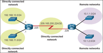
Figure one-33 Directly Continued and Remote Network Routes
Routing Table Sources (1.3.1.2)
On a Cisco router, the show ip route control is used to display the IPv4 routing tabular array of a router. A router provides boosted route information, including how the route was learned, how long the route has been in the table, and which specific interface to use to go to a predefined destination.
Entries in the routing table tin be added as follows:
-
Local route interfaces —Added when an interface is configured and active. This entry is only displayed in IOS 15 or newer for IPv4 routes and all IOS releases for IPv6 routes.
-
Straight connected interfaces —Added to the routing table when an interface is configured and active.
-
Static routes—Added when a route is manually configured and the exit interface is active.
-
Dynamic routing protocol—Added when routing protocols that dynamically learn about the network, such as EIGRP and OSPF, are implemented and networks are identified.
The sources of the routing tabular array entries are identified by a code. The code identifies how the road was learned. For instance, common codes include the following:
-
L—Identifies the address assigned to a router'southward interface. This allows the router to efficiently make up one's mind when it receives a bundle for the interface instead of being forwarded.
-
C—Identifies a directly connected network.
-
S—Identifies a static route created to reach a specific network.
-
D—Identifies a dynamically learned network from another router using EIGRP.
-
O—Identifies a dynamically learned network from another router using the OSPF routing protocol.
Case 1-fourteen shows the routing table for the R1 router in Effigy 1-20.
Case ane-14 Routing Table for R1
R1# show ip route Codes: L - local, C - connected, South - static, R - RIP, Thousand - mobile, B - BGP D - EIGRP, EX - EIGRP external, O - OSPF, IA - OSPF inter surface area N1 - OSPF NSSA external type 1, N2 - OSPF NSSA external type 2 E1 - OSPF external type 1, E2 - OSPF external type 2, East - EGP i - IS-IS, L1 - IS-IS level-one, L2 - IS-IS level-2, ia - IS-IS inter area * - candidate default, U - per-user static route, o - ODR P - periodic downloaded static route Gateway of last resort is not set 10.0.0.0/24 is subnetted, 2 subnets D 10.1.ane.0/24 [90/2170112] via 209.165.200.226, 00:01:30, Serial0/0/0 D ten.1.2.0/24 [ninety/2170112] via 209.165.200.226, 00:01:xxx, Serial0/0/0 192.168.10.0/24 is variably subnetted, 2 subnets, ii masks C 192.168.ten.0/24 is directly connected, GigabitEthernet0/0 L 192.168.10.1/32 is direct connected, GigabitEthernet0/0 192.168.11.0/24 is variably subnetted, 2 subnets, 2 masks C 192.168.eleven.0/24 is directly connected, GigabitEthernet0/ane 50 192.168.xi.1/32 is directly continued, GigabitEthernet0/1 209.165.200.0/24 is variably subnetted, two subnets, 2 masks C 209.165.200.224/thirty is directly connected, Serial0/0/0 50 209.165.200.225/32 is directly connected, Serial0/0/0 R1#
Remote Network Routing Entries (1.3.1.three)
Every bit a network administrator, information technology is imperative to know how to translate the content of IPv4 and IPv6 routing tables. Figure 1-34 displays an IPv4 routing tabular array entry on R1 for the route to remote network 10.ane.one.0.
Table i-5 describes the parts of the routing table entry shown in Effigy ane-34.
Table 1-5 Parts of a Remote Network Entry
| Fable | Name | Description |
| A | Route Source | Identifies how the route was learned. |
| B | Destination Network | Identifies the IPv4 address of the remote network. |
| C | Authoritative Distance | Identifies the trustworthiness of the road source. |
| D | Metric | Identifies the value assigned to reach the remote network. Lower values indicate preferred routes. |
| E | Side by side Hop | Identifies the IPv4 address of the adjacent router to forward the parcel to. |
| F | Route Timestamp | Identifies how much time has passed since the route was learned. |
| 1000 | Outgoing Interface | Identifies the exit interface to apply to forward a packet toward the final destination. |
Directly Continued Routes (1.3.ii)
In this topic you volition learn how a router builds a routing table of directly continued networks.
Directly Connected Interfaces (i.3.2.1)
A newly deployed router, without configured interfaces, has an empty routing table, equally shown in Instance 1-15.
Case 1-fifteen Empty Routing Table
R1# prove ip route Codes: L - local, C - connected, S - static, R - RIP, M - mobile, B - BGP D - EIGRP, EX - EIGRP external, O - OSPF, IA - OSPF inter expanse N1 - OSPF NSSA external blazon i, N2 - OSPF NSSA external blazon two E1 - OSPF external type 1, E2 - OSPF external type 2, Eastward - EGP i - IS-IS, L1 - IS-IS level-1, L2 - IS-IS level-ii, ia - IS-IS inter area * - candidate default, U - per-user static route, o - ODR P - periodic downloaded static road Gateway of concluding resort is not set R1#
Before the interface state is considered upward/up and added to the IPv4 routing table, the interface must
-
Be assigned a valid IPv4 or IPv6 address
-
Exist activated with the no shutdown control
-
Receive a carrier signal from another device (router, switch, host, and so on)
When the interface is up, the network of that interface is added to the routing table as a directly connected network.
Straight Connected Routing Table Entries (1.3.2.2)
An active, properly configured, directly continued interface actually creates two routing table entries. Figure 1-35 displays the IPv4 routing table entries on R1 for the directly connected network 192.168.x.0.
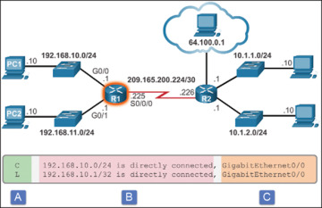
Figure i-35 Directly Connected Network Entry Identifiers
The routing table entry for directly connected interfaces is simpler than the entries for remote networks. Table ane-6 describes the parts of the routing table entry shown in Effigy ane-35.
Tabular array 1-6 Parts of a Directly Connected Network Entry
| Fable | Name | Description |
| A | Route Source | Identifies how the network was learned by the router.Directly connected interfaces accept ii route source codes. 'C' identifies a directly connected network. '50' identifies the IPv4 accost assigned to the router's interface. |
| B | Destination Network | Identifies the destination network and how it is connected. |
| C | Approachable Interface | Identifies the exit interface to employ when forwarding packets to the destination network. |
Straight Continued Examples (1.3.ii.three)
Case 1-xvi shows the steps to configure and activate the interfaces fastened to R1 in Figure 1-20. Find the Layer ane and two advisory letters generated as each interface is activated.
Example 1-xvi Configuring the Straight Connected IPv4 Interfaces
R1(config)# interface gigabitethernet 0/0 R1(config-if)# description Link to LAN i R1(config-if)# ip address 192.168.10.1 255.255.255.0 R1(config-if)# no shutdown R1(config-if)# get out *Feb one 13:37:35.035: %LINK-3-UPDOWN: Interface GigabitEthernet0/0, changed country to down *February 1 13:37:38.211: %LINK-3-UPDOWN: Interface GigabitEthernet0/0, changed state to upwards *Feb 1 13:37:39.211: %LINEPROTO-5-UPDOWN: Line protocol on Interface Gigabit Ethernet0/0, changed state to upward R1(config)# interface gigabitethernet 0/1 R1(config-if)# clarification Link to LAN 2 R1(config-if)# ip address 192.168.eleven.one 255.255.255.0 R1(config-if)# no shutdown R1(config-if)# leave *Feb 1 13:38:01.471: %LINK-iii-UPDOWN: Interface GigabitEthernet0/1, changed state to down *Feb i 13:38:04.211: %LINK-3-UPDOWN: Interface GigabitEthernet0/1, inverse country to upward *Feb one 13:38:05.211: %LINEPROTO-5-UPDOWN: Line protocol on Interface Gigabit Ethernet0/ane, changed state to up R1(config)# interface serial 0/0/0 R1(config-if)# description Link to R1 R1(config-if)# ip address 209.165.200.225 255.255.255.252 R1(config-if)# clock rate 128000 R1(config-if)# no shutdown R1(config-if)# end *February 1 13:38:22.723: %LINK-iii-UPDOWN: Interface Serial0/0/0, changed land to upwards *February 1 13:38:23.723: %LINEPROTO-five-UPDOWN: Line protocol on Interface Serial0/0/0, changed state to upwardly R1#
As each interface is added, the routing tabular array automatically adds the connected ('C') and local ('Fifty') entries. Example 1-17 provides an example of the routing table with the direct connected interfaces of R1 configured and activated.
Example 1-17 Verifying the Directly Continued Routing Table Entries
R1# show ip route | brainstorm Gateway Gateway of terminal resort is not set 192.168.x.0/24 is variably subnetted, 2 subnets, 2 masks C 192.168.x.0/24 is directly connected, GigabitEthernet0/0 L 192.168.x.1/32 is directly connected, GigabitEthernet0/0 192.168.xi.0/24 is variably subnetted, ii subnets, two masks C 192.168.11.0/24 is straight connected, GigabitEthernet0/one L 192.168.11.1/32 is straight connected, GigabitEthernet0/1 209.165.200.0/24 is variably subnetted, 2 subnets, 2 masks C 209.165.200.224/30 is directly connected, Serial0/0/0 50 209.165.200.225/32 is directly connected, Serial0/0/0 R1#
Directly Continued IPv6 Example (ane.3.2.4)
Example i-18 shows the configuration steps for the directly connected interfaces of R1 in Figure 1-21 with the indicated IPv6 addresses. Notice the Layer 1 and Layer 2 informational letters generated equally each interface is configured and activated.
Example i-xviii Configuring the Directly Continued IPv6 Interfaces
R1(config)# interface gigabitethernet 0/0 R1(config-if)# description Link to LAN one R1(config-if)# ipv6 address 2001:db8:acad:one::one/64 R1(config-if)# no shutdown R1(config-if)# leave *February iii 21:38:37.279: %LINK-3-UPDOWN: Interface GigabitEthernet0/0, changed state to down *Feb three 21:38:forty.967: %LINK-iii-UPDOWN: Interface GigabitEthernet0/0, inverse state to upwards *Feb 3 21:38:41.967: %LINEPROTO-5-UPDOWN: Line protocol on Interface GigabitEther- net0/0, changed state to upwardly R1(config)# interface gigabitethernet 0/one R1(config-if)# description Link to LAN 2 R1(config-if)# ipv6 accost 2001:db8:acad:2::1/64 R1(config-if)# no shutdown R1(config-if)# leave *Feb 3 21:39:21.867: %LINK-iii-UPDOWN: Interface GigabitEthernet0/1, changed state to down *Feb three 21:39:24.967: %LINK-three-UPDOWN: Interface GigabitEthernet0/1, changed state to up *Feb three 21:39:25.967: %LINEPROTO-five-UPDOWN: Line protocol on Interface Gigabit Ethernet0/1, inverse state to upwards R1(config)# interface serial 0/0/0 R1(config-if)# description Link to R2 R1(config-if)# ipv6 address 2001:db8:acad:three::1/64 R1(config-if)# clock rate 128000 R1(config-if)# no shutdown *February iii 21:39:43.307: %LINK-3-UPDOWN: Interface Serial0/0/0, changed state to down R1(config-if)# terminate R1#
The show ipv6 route command shown in Example 1-19 is used to verify that IPv6 networks and specific IPv6 interface addresses have been installed in the IPv6 routing table. Similar IPv4, a 'C' next to a route indicates that this is a directly connected network. An 'Fifty' indicates the local route. In an IPv6 network, the local road has a /128 prefix. Local routes are used past the routing tabular array to efficiently process packets with a destination accost of the interface of the router.
Example ane-19 Verifying IPv6 Routing Table
R1# bear witness ipv6 road IPv6 Routing Table - default - v entries Codes: C - Connected, 50 - Local, S - Static, U - Per-user Static route B - BGP, R - RIP, H - NHRP, I1 - ISIS L1 I2 - ISIS L2, IA - ISIS interarea, IS - ISIS summary, D - EIGRP EX - EIGRP external, ND - ND Default, NDp - ND Prefix, DCE - Destination NDr - Redirect, O - OSPF Intra, OI - OSPF Inter, OE1 - OSPF ext 1 OE2 - OSPF ext two, ON1 - OSPF NSSA ext 1, ON2 - OSPF NSSA ext ii C 2001:DB8:ACAD:1::/64 [0/0] via GigabitEthernet0/0, directly connected L 2001:DB8:ACAD:1::1/128 [0/0] via GigabitEthernet0/0, receive C 2001:DB8:ACAD:ii::/64 [0/0] via GigabitEthernet0/ane, directly continued L 2001:DB8:ACAD:two::1/128 [0/0] via GigabitEthernet0/1, receive L FF00::/8 [0/0] via Null0, receive R1#
Observe that at that place is too a route installed to the FF00::/8 network. This route is required for multicast routing.
Example 1-xx displays how the show ipv6 route control tin can be combined with a specific network destination to display the details of how the router learned that route.
Case one-twenty Verifying a Single IPv6 Road Entry
R1# show ipv6 route 2001:db8:acad:1::/64 Routing entry for 2001:DB8:ACAD:1::/64 Known via "connected", distance 0, metric 0, type connected Road count is ane/1, share count 0 Routing paths: direct connected via GigabitEthernet0/0 Terminal updated 03:14:56 ago R1#
Example 1-21 displays how connectivity to R2 can be verified using the ping control. Notice what happens when the G0/0 LAN interface of R2 is the target of the ping command. The pings are unsuccessful. This is because R1 does not take an entry in the routing tabular array to reach the 2001:DB8:ACAD:iv::/64 network.
Instance 1-21 Testing Connectivity to R2
R1# ping 2001:db8:acad:3::2 Type escape sequence to abort. Sending five, 100-byte ICMP Echos to 2001:DB8:ACAD:3::2, timeout is 2 seconds: !!!!! Success rate is 100 percent (5/5), round-trip min/avg/max = 12/13/xvi ms R1# ping 2001:db8:acad:4::1 Blazon escape sequence to abort. Sending 5, 100-byte ICMP Echos to 2001:DB8:ACAD:4::one, timeout is 2 seconds: % No valid route for destination Success rate is 0 percent (0/1) R1#
R1 requires additional information to achieve a remote network. Remote network road entries can exist added to the routing tabular array using either of the following:
-
Static routing
-
Dynamic routing protocols
Statically Learned Routes (1.3.3)
In this topic you will learn how a router builds a routing table using static routes.
Static Routes (i.3.3.1)
After directly continued interfaces are configured and added to the routing tabular array, static or dynamic routing can exist implemented.
Static routes are manually configured. They define an explicit path between ii networking devices. Dissimilar a dynamic routing protocol, static routes are not automatically updated and must be manually reconfigured if the network topology changes. The benefits of using static routes include improved security and resources efficiency. Static routes use less bandwidth than dynamic routing protocols, and no CPU cycles are used to calculate and communicate routes. The main disadvantage to using static routes is the lack of automated reconfiguration if the network topology changes.
There are two common types of static routes in the routing table:
-
Static road to a specific network
-
Default static route
A static route can be configured to attain a specific remote network. IPv4 static routes are configured using the following command:
Router(config)# ip road network mask { side by side-hop-ip | get out-intf } A static route is identified in the routing table with the lawmaking 'Due south.'
A default static road is similar to a default gateway on a host. The default static route specifies the go out point to use when the routing tabular array does not incorporate a path for the destination network. A default static route is useful when a router has only one exit signal to some other router, such equally when the router connects to a central router or service provider.
To configure an IPv4 default static route, use the following control:
Router(config)# ip road 0.0.0.0 0.0.0.0 { exit-intf | adjacent-hop-ip } Effigy 1-36 provides a simple scenario of how default and static routes can exist applied.
Static Route Examples (1.three.3.2)
Example 1-22 shows the configuration and verification of an IPv4 default static route on R1 from Figure 1-20. The static route is using Series 0/0/0 as the exit interface. Discover that the configuration of the route generated an 'S*' entry in the routing table. The 'S' signifies that the road source is a static route, whereas the asterisk (*) identifies this road as a possible candidate to exist the default road. In fact, it has been chosen equally the default road equally evidenced by the line that reads, "Gateway of Last Resort is 0.0.0.0 to network 0.0.0.0."
Example 1-22 Configuring and Verifying a Default Static IPv4 Road
R1(config)# ip route 0.0.0.0 0.0.0.0 Serial0/0/0 R1(config)# exit R1# *Feb 1 10:nineteen:34.483: %SYS-v-CONFIG_I: Configured from console by console R1# prove ip route | begin Gateway Gateway of terminal resort is 0.0.0.0 to network 0.0.0.0 Southward* 0.0.0.0/0 is direct connected, Serial0/0/0 192.168.10.0/24 is variably subnetted, 2 subnets, two masks C 192.168.x.0/24 is directly connected, GigabitEthernet0/0 L 192.168.x.1/32 is directly connected, GigabitEthernet0/0 192.168.eleven.0/24 is variably subnetted, 2 subnets, ii masks C 192.168.xi.0/24 is straight continued, GigabitEthernet0/1 L 192.168.11.1/32 is directly connected, GigabitEthernet0/1 209.165.200.0/24 is variably subnetted, 2 subnets, 2 masks C 209.165.200.224/xxx is directly continued, Serial0/0/0 Fifty 209.165.200.225/32 is directly continued, Serial0/0/0 R1#
Example ane-23 shows the configuration and verification of two static routes from R2 to reach the two LANs on R1. The route to 192.168.10.0/24 has been configured using the exit interface while the route to 192.168.eleven.0/24 has been configured using the next-hop IPv4 address. Although both are adequate, there are some differences in how they operate. For instance, discover how different they await in the routing tabular array. Also detect that considering these static routes were to specific networks, the output indicates that the Gateway of Last Resort is not set.
Example 1-23 Configuring and Verifying Static IPv4 Routes
R2(config)# ip route 192.168.10.0 255.255.255.0 s0/0/0 R2(config)# ip route 192.168.eleven.0 255.255.255.0 209.165.200.225 R2(config)# exit R2# R2# testify ip road | brainstorm Gateway Gateway of last resort is not set x.0.0.0/8 is variably subnetted, 4 subnets, 2 masks C ten.ane.one.0/24 is directly connected, GigabitEthernet0/0 50 10.1.1.ane/32 is directly continued, GigabitEthernet0/0 C 10.1.2.0/24 is direct connected, GigabitEthernet0/1 L 10.1.2.1/32 is directly connected, GigabitEthernet0/1 S 192.168.x.0/24 is directly continued, Serial0/0/0 Southward 192.168.xi.0/24 [one/0] via 209.165.200.225 209.165.200.0/24 is variably subnetted, 2 subnets, ii masks C 209.165.200.224/xxx is directly connected, Serial0/0/0 L 209.165.200.226/32 is directly continued, Serial0/0/0 R2#
Static IPv6 Route Examples (1.3.three.3)
Like IPv4, IPv6 supports static and default static routes. They are used and configured similar IPv4 static routes.
To configure a default static IPv6 route, use the ipv6 road ::/0 {ipv6-accost | interface-type interface-number} global configuration control.
Case ane-24 shows the configuration and verification of a default static road on R1 from Figure 1-21. The static route is using Series 0/0/0 as the get out interface.
Example 1-24 Configuring and Verifying a Default Static IPv6 Route
R1(config)# ipv6 route ::/0 s0/0/0 R1(config)# get out R1# show ipv6 route IPv6 Routing Tabular array - default - viii entries Codes: C - Connected, L - Local, S - Static, U - Per-user Static road B - BGP, R - RIP, H - NHRP, I1 - ISIS L1 I2 - ISIS L2, IA - ISIS interarea, IS - ISIS summary, D - EIGRP EX - EIGRP external, ND - ND Default, NDp - ND Prefix, DCE - Destination NDr - Redirect, O - OSPF Intra, OI - OSPF Inter, OE1 - OSPF ext 1 OE2 - OSPF ext 2, ON1 - OSPF NSSA ext one, ON2 - OSPF NSSA ext 2 South ::/0 [i/0] via Serial0/0/0, directly connected <output omitted>
Notice in the output that the default static route configuration generated an 'S' entry in the routing table. The 'S' signifies that the route source is a static route. Unlike the IPv4 static route, there is no asterisk (*) or Gateway of Last Resort explicitly identified.
Similar IPv4, static routes are routes explicitly configured to reach a specific remote network. Static IPv6 routes are configured using the ipv6 route ipv6-prefix/prefix-length {ipv6-address|interface-type interface-number} global configuration control.
Case 1-25 shows the configuration and verification of two static routes from R2 to attain the 2 LANs on R1. The route to the 2001:0DB8:ACAD:2::/64 LAN is configured with an exit interface, whereas the route to the 2001:0DB8:ACAD:1::/64 LAN is configured with the next-hop IPv6 accost. The next-hop IPv6 address tin can exist either an IPv6 global unicast or a link-local address.
Example 1-25 Configuring and Verifying Static IPv6 Routes
R2(config)# ipv6 route 2001:DB8:ACAD:1::/64 2001:DB8:ACAD:3::1 R2(config)# ipv6 road 2001:DB8:ACAD:ii::/64 s0/0/0 R2(config)# finish R2# show ipv6 route IPv6 Routing Table - default - 9 entries Codes: C - Connected, Fifty - Local, S - Static, U - Per-user Static route B - BGP, R - RIP, H - NHRP, I1 - ISIS L1 I2 - ISIS L2, IA - ISIS interarea, IS - ISIS summary, D - EIGRP EX - EIGRP external, ND - ND Default, NDp - ND Prefix, DCE - Destination NDr - Redirect, O - OSPF Intra, OI - OSPF Inter, OE1 - OSPF ext 1 OE2 - OSPF ext ii, ON1 - OSPF NSSA ext i, ON2 - OSPF NSSA ext two South 2001:DB8:ACAD:ane::/64 [i/0] via 2001:DB8:ACAD:3::1 Southward 2001:DB8:ACAD:2::/64 [1/0] via Serial0/0/0, straight connected <output omitted>
Example one-26 confirms remote network connectivity to the 2001:0DB8:ACAD:4::/64 LAN on R2 from R1.
Example i-26 Verify Connectivity to Remote Network
R1# ping 2001:db8:acad:4::1 Blazon escape sequence to abort. Sending 5, 100-byte ICMP Echos to 2001:DB8:ACAD:4::1, timeout is 2 seconds: !!!!! Success charge per unit is 100 pct (5/5), round-trip min/avg/max = 12/13/16 ms R1#
Dynamic Routing Protocols (1.3.iv)
In this topic y'all will learn how a router builds a routing table using dynamic routes.
Dynamic Routing (i.3.four.1)
Dynamic routing protocols are used by routers to share information about the reachability and status of remote networks. Dynamic routing protocols perform several activities, including network discovery and maintaining routing tables.
Network discovery is the ability of a routing protocol to share data about the networks that information technology knows about with other routers that are as well using the same routing protocol. Instead of depending on manually configured static routes to remote networks on every router, a dynamic routing protocol allows the routers to automatically acquire about these networks from other routers. These networks, and the best path to each, are added to the routing table of the router and identified equally a network learned by a specific dynamic routing protocol.
During network discovery, routers exchange routes and update their routing tables. Routers accept converged subsequently they have finished exchanging and updating their routing tables. Routers then maintain the networks in their routing tables.
Figure 1-37 provides a simple scenario of how 2 neighboring routers would initially exchange routing information. In this simplified commutation, R1 introduces itself and the networks it can reach. R2 responds with its list of networks.
IPv4 Routing Protocols (one.three.4.2)
A router running a dynamic routing protocol does not but make a best path determination to a network; it also determines a new best path if the initial path becomes unusable (or if the topology changes). For these reasons, dynamic routing protocols take an advantage over static routes. Routers that utilize dynamic routing protocols automatically share routing information with other routers and recoup for any topology changes without involving the network administrator.
Cisco routers tin can support a variety of dynamic IPv4 routing protocols, including these:
-
EIGRP—Enhanced Interior Gateway Routing Protocol
-
OSPF—Open Shortest Path Starting time
-
IS-IS—Intermediate System-to-Intermediate Organization
-
RIP—Routing Data Protocol
To decide which routing protocols the IOS supports, utilise the router ? command in global configuration mode, every bit shown in Instance ane-27.
Example i-27 IPv4 Routing Protocols
R1(config)# router ? bgp Border Gateway Protocol (BGP) eigrp Enhanced Interior Gateway Routing Protocol (EIGRP) isis ISO IS-IS iso-igrp IGRP for OSI networks mobile Mobile routes odr On Demand stub Routes ospf Open Shortest Path Outset (OSPF) ospfv3 OSPFv3 rip Routing Data Protocol (RIP) R1(config)# router
IPv4 Dynamic Routing Examples (1.3.4.three)
In this dynamic routing example, presume that R1 and R2 take been configured to support the dynamic routing protocol EIGRP. R2 now has a connexion to the Internet, as shown in Figure 1-38. The routers likewise advertise directly continued networks. R2 advertises that it is the default gateway to other networks.
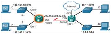
Effigy 1-38 IPv4 Topology with Connection to the Net
The output in Example 1-28 displays the routing table of R1 later on the routers accept exchanged updates and converged.
Example 1-28 Verify Dynamic IPv4 Routes
R1# evidence ip route | brainstorm Gateway Gateway of concluding resort is 209.165.200.226 to network 0.0.0.0 D*EX 0.0.0.0/0 [170/2297856] via 209.165.200.226, 00:07:29, Serial0/0/0 10.0.0.0/24 is subnetted, 2 subnets D ten.1.1.0 [90/2172416] via 209.165.200.226, 00:07:29, Serial0/0/0 D 10.1.2.0 [xc/2172416] via 209.165.200.226, 00:07:29, Serial0/0/0 192.168.10.0/24 is variably subnetted, 2 subnets, two masks C 192.168.10.0/24 is directly continued, GigabitEthernet0/0 L 192.168.ten.i/32 is direct connected, GigabitEthernet0/0 192.168.11.0/24 is variably subnetted, 2 subnets, 2 masks C 192.168.11.0/24 is directly connected, GigabitEthernet0/1 L 192.168.11.ane/32 is directly connected, GigabitEthernet0/one 209.165.200.0/24 is variably subnetted, two subnets, 2 masks C 209.165.200.224/30 is directly connected, Serial0/0/0 L 209.165.200.225/32 is direct continued, Serial0/0/0 R1#
Along with the connected and link-local interfaces, there are three 'D' entries in the routing table.
-
The entry starting time with 'D*EX' identifies that the source of this entry was EIGRP ('D'). The route is a candidate to exist a default route ('*'), and the route is an external road ('*EX') forwarded by EIGRP.
-
The other ii 'D' entries are routes installed in the routing tabular array based on the update from R2 advert its LANs.
IPv6 Routing Protocols (1.three.4.4)
ISR devices support the dynamic IPv6 routing protocols shown in Example 1-29.
Example 1-29 IPv6 Routing Protocols
R1(config)# ipv6 router ? eigrp Enhanced Interior Gateway Routing Protocol (EIGRP) ospf Open Shortest Path Beginning (OSPF) rip IPv6 Routing Information Protocol (RIPv6) R1(config)# ipv6 router
Support for dynamic IPv6 routing protocols is dependent on hardware and IOS version. Nearly of the modifications in the routing protocols are to support the longer IPv6 addresses and unlike header structures.
IPv6 routing is not enabled by default. Therefore, to enable IPv6 routers to frontward traffic, y'all must configure the ipv6 unicast-routing global configuration command.
IPv6 Dynamic Routing Examples (ane.3.4.v)
Routers R1 and R2 in Figure 1-21 have been configured with the dynamic routing protocol EIGRP for IPv6. (This is the IPv6 equivalent of EIGRP for IPv4.)
To view the routing tabular array on R1, enter the show ipv6 route control, as shown in Example 1-30.
Example 1-30 Verify Dynamic IPv6 Routes
R1# testify ipv6 road IPv6 Routing Tabular array - default - ix entries Codes: C - Connected, L - Local, Southward - Static, U - Per-user Static road B - BGP, R - RIP, H - NHRP, I1 - ISIS L1 I2 - ISIS L2, IA - ISIS interarea, IS - ISIS summary, D - EIGRP EX - EIGRP external, ND - ND Default, NDp - ND Prefix, DCE - Destination NDr - Redirect, O - OSPF Intra, OI - OSPF Inter, OE1 - OSPF ext 1 OE2 - OSPF ext 2, ON1 - OSPF NSSA ext one, ON2 - OSPF NSSA ext ii C 2001:DB8:ACAD:one::/64 [0/0] via GigabitEthernet0/0, direct connected Fifty 2001:DB8:ACAD:1::1/128 [0/0] via GigabitEthernet0/0, receive C 2001:DB8:ACAD:2::/64 [0/0] via GigabitEthernet0/one, direct connected Fifty 2001:DB8:ACAD:two::1/128 [0/0] via GigabitEthernet0/1, receive C 2001:DB8:ACAD:3::/64 [0/0] via Serial0/0/0, directly connected L 2001:DB8:ACAD:three::1/128 [0/0] via Serial0/0/0, receive D 2001:DB8:ACAD:4::/64 [90/2172416] via FE80::D68C:B5FF:FECE:A120, Serial0/0/0 D 2001:DB8:ACAD:five::/64 [90/2172416] via FE80::D68C:B5FF:FECE:A120, Serial0/0/0 L FF00::/8 [0/0] via Null0, receive R1#
The output shows the routing table of R1 after the routers take exchanged updates and converged. Along with the continued and local routes, there are two 'D' entries (EIGRP routes) in the routing table.

Source: https://www.ciscopress.com/articles/article.asp?p=2756479&seqNum=6
Posted by: jeffreycomman99.blogspot.com
0 Response to "What Code Is Used In The Routing Table To Identify Routes Learned Through Eigrp?"
Post a Comment